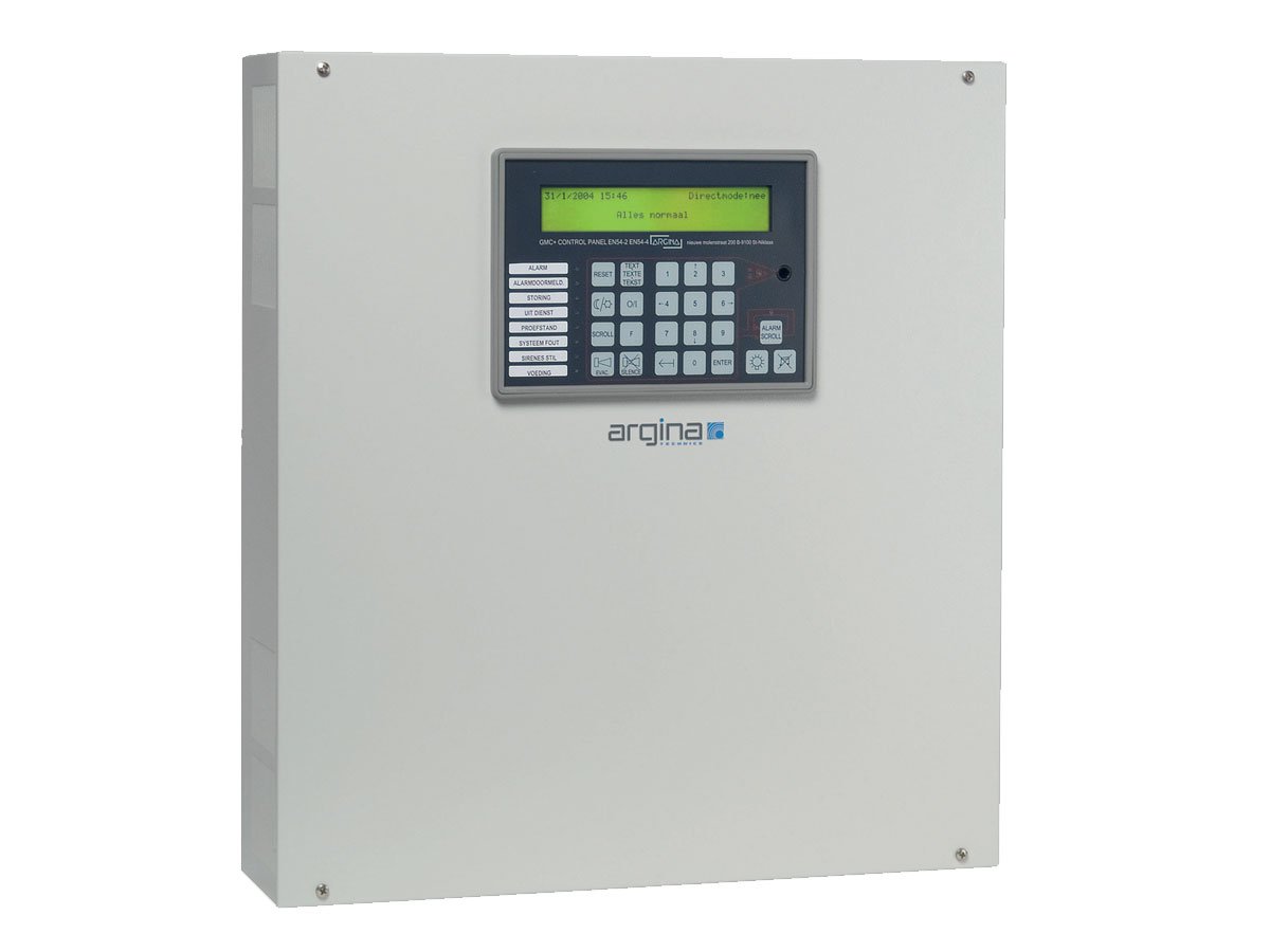
Sophisticated hardware and software have created a control panel with unprecedented facilities in a compact housing.
- Installer-friendly fitting
- Simple operation
- Clear indications
- Large display with backlight
- One-key language change
- Conforms to EN54-2/4
- BOSEC approved
- Multi-microprocessor design
- Single board module
- Alarm identification with analogue analysis
The control unit is available with or without an integrated control panel.
The control unit communicates fully bidirectionally with the entire range of Argina detectors, manual fire alarms, input/output modules and gas detectors.
Fire alarm installations with from 1 to 10,000 detectors can be connected to the GMC+ control unit.
Control units can have practically unlimited connections to each other or to one or more control panels via the ArgNet.
Where necessary, ArgNet interfaces can be used to enable local connections:
- PC via a USB interface
- Pager via RS232 interface
- Printer via RS232 interface
- LON via ArgLon interface
The control panel can be surface mounted or built in. The control panel works with 24Vdc or 230V power supply/charger and a backup battery. Only a connection to the ArgNet is required.
Options
- Audio interface: The control unit has a built-in audio interface, which is used to connect it to a PA system. The control unit can send pre-recorded messages and even indicate where the alarm has occurred.
- Modem module: It can be equipped with a modem module giving the following options:
- automatic telephone fire report with voice
- automatic telephone connection to compatible control rooms
- remote maintenance and updating of the control unit
The bi-directional loops are physical twisted pairs and are fully compatible with short-circuit isolators.
If the loop is confi gured as a closed loop, then it will be fed from both sides in the event of a line break, so that all detectors and manual alarms remain active. If a short circuit occurs, only that part of the loop between the two short-circuit modules where it happens will be disabled.
The loops interface with analogue detectors, which are identifiable measuring devices that continuously send their analogue readings to the control unit via digital communication. The control unit uses several successive readings and specific algorithms to determine whether a detector is sending an alarm or is faulty.
The control unit interprets data in the long term as well so that preventive maintenance can be carried out. The language the control panel uses for messages can be changed at any time by using a single key. A precise indication of the location is given in each report (this text, provided by the user and up to 40 characters long, remains unchanged).
The control unit has 11 freely-configurable relays as standard. It can have 2 additional relay PCBs fitted as an option, each one having 12 additional relays (1A/relay), Relays can be located remotely by using input/output modules in the loops. The control unit has 4 universal inputs:
- Two monitored inputs for connecting, for example, an external reset switch.
- Two universal optocoupler inputs.
The inputs can be expanded, for example with 4 additional inputs per relay extension PCB, or with remotely-located input/output modules.
The control unit can be configured fully and quickly using the Confi-GMC program on a PC.
A laptop PC can be plugged into a control panel for commissioning or during maintenance without opening the control unit. All internal readings can be retrieved via the laptop, for example the readings from the detectors, the power consumption in the loops and the power consumption by external users.
Simple settings such as delay times can be entered from the control panel.
The various authorisation levels (EN54-2):
- Level 1: Four keys accessible by everyone: alarm scroll, lamp test, buzzer silence, language setting.
- Level 2: The other keys are accessible when the special key is inserted in the keypad and is turned in the right direction.
- Level 3: Some F-key functions are possible only after a code has been entered.
- Level 4: By plugging in a laptop with the Confi-GMC program.
The ArgNet network connects to the GMC+ fire alarm control units, the control panels and the Arg-Net interfaces. The ArgNet network uses screened twisted pair cables and is not polarised.
A second cable, connected to the ArgNet Backup clips, can be used for increased reliability or if an approvals body requires it. If communication on the first network is not possible, all units switch over to the backup network, so that the entire system remains operational, even in the event of a line break or a short circuit in a network.
HOUSING
- Dimensions: 457 x 500 x 113mm (width x height x depth)
- Colour: light beige (RAL7035)
- Material: ABS/V0
- Fixing: 4 holes 5mm diameter
- Cable entry:
- 2 centrally-located entry areas at the back of the base. (The top and bottom of the cover have 26mm cutouts. The base creates a 26mm gap between the casing and the wall. This allows the cables to be brought from above or below, to pass behind the casing and to enter via the central cable entry in the casing. Grommets are not required.)
- lP rating: IP30
- 19” compatibility: The casing can be mounted in a 19” rack using an adapter and a suitable cover plate.
- Place for batteries inside: for a maximum of two 17Ah lead-acid batteries (each 180x170x78 mm)
- Temperature: -5°C to +45°C
- Humidity: 0-95% (non-condensing)
POWER SUPPLY VOLTAGE
- Primary: 230VAC / fuse 2AT
- Batteries: 24VDC hermetically-sealed lead-acid batteries (2 x 12V in series)
- Battery capacity: 17Ah
- Battery charging voltage: temperature-dependent regulated for maximum service life of batteries (between 26.5 and 28V)
- Battery charging current: max.1.4 A (limited internally)
CONTROL PANEL POWER
- If fitted in the front of the control unit: only 24V from the control unit
- If located remotely:
- primary supply: 230VAC or 24VDC according to choice
- secondary supply: internal small lead-acid battery
POWER SUPPLY OUTPUT
- Quantity: 4
- Fuse per output: 5AF
- Voltage: +24V (28.5V with mains supply, 19 to 24V during battery changeover)power consumption of the control unit itself (if battery powered) 125mA (plus 25mA per activated relay)
- Total permitted power supply load: 2A (4A in the event of an alarm)
- Permitted current for external users: the total permitted power supply load minus the power consumption of the control unit itself and minus the power consumption in the loops
FIRE DETECTION LOOPS
- Quantity: 6 bi-directional, each with a return loop
- Number of encoders per loop: max 124
- Short circuit limit: 500mA
RELAYS
- 5 relays with: 2 switch-over contacts 5A / 24V
- 6 relays with: 1 switch-over contact 5A / 24V
INPUTS
- 2 monitored inputs: each one monitors short circuits and line breaks
- end of line resistor = 22K
- active resistance = 4K7
- 2 optocoupler inputs: 5 .. 24V AC or DC
- Inputs on control panel: monitored switch loop with resistance indication for reading 2 external switches (for example external Reset and Silence)
MONITORING INPUTS
- 4 monitoring inputs: for monitoring cabling to siren test, for example, and for line breaks and short circuits
- end of line resistor = 470 ohm / 2W
OPTIONS
- Audio Output: Cinch connector
- Output impedance: 600 ohm, balanced (transformer coupled)
- Level: 2.2V p-p (= 0.77Veff , = -2dBV, = 0dBm) into 600 ohm
- Relay Module with 12 relays and 4 inputs
MODEM
- Connectors: terminal blocks for Line In and Line Out-
- Type: V.34 / 33K6 or better
- Approval: world class, CTR21
- Connection: Direct analogue outside line (POTS)